Artesyn.com, SLPower.com, and TEGAM.com are now part of AdvancedEnergy.com. Learn more

.jpg?lang=en-us)
.jpg?lang=en-us)
Precision. Power. Performance. Trust.
Cutting-Edge Products from the Innovation Powerhouse
.png?resizemode=force&maxsidesize=408)
New & Featured Applications
Explore All Applications


Analytical Instruments
Advanced Energy's power solutions are designed to meet the specific power requirements of various analytical instruments such as spectroscopy, mass spectrometry, chromatography, electrophoresis, particle size analyzers, and scanning electron microscopes.
Explore Analytical Instruments
Featured Videos
View All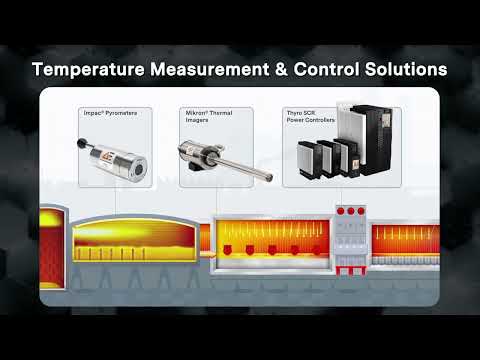

Close Popup

Introducing ConfigPro
Advanced Energy’s Revolutionary Online Power Configurator
With over 3 million configurable power supply combinations, this power solution algorithm optimizes cost and guides you to the ideal solution for MP, IMP, IVS, and MICROMP (UMP) configurable power supply families.
Get Started
Latest from Advanced Energy
All News & Events
Blog
Reliability in Healthcare: The Vital Role of Voltage Regulation
May 16, 2024
In operating rooms, every device’s performance is critical and essential to a patient’s survival. Dialysis centers require precise readings to administer crucial treatment, and in emergency rooms, the reliability of electrical equipment is quite literally a matter of life and death.

News
Advanced Energy to Participate at Upcoming Investor Conferences
May 10, 2024
Advanced Energy today announced that it will participate at the following investor conferences. JP Morgan 51st Annual Global Technology, Media and Communications Conference Date: Monday, May 20, 2024 Presentation time: 2:30PM EST KeyBanc Industrials & ...
News
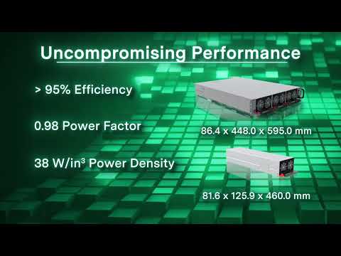
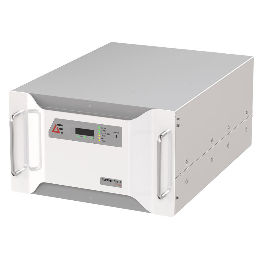
Advanced Energy Introduces Intelligent, Fully Water-Cooled DC Power Supply
May 07, 2024
AEI has added a fully water-cooled 60 kW option to its Ascent® Arc Management System™ (AMS) family of DC generators for the precise control of film quality and repeatability, extending the industry-leading system with the most advanced software capabilities and the ability to operate in harsh environments.